MOHR'S CIRCLE FOR SPECIAL STRESS CONDITIONS
Mohr's circle is used here to demonstrate the relationship among the applied stresses, the principal stresses, and the maximum shear stress for the following special cases:
Pure uniaxial tension
Pure uniaxial compression
Pure torsional shear
Uniaxial tension combined with torsional shear
These are important, frequently encountered stress conditions, and they will be used in later chapters to illustrate failure theories and design methods. These failure theories are based on the values of the principal stresses and the maximum shear stress.
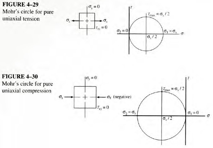
Pure Uniaxial Tension
The stress condition produced in all parts of a standard tensile test specimen is pure uniaxial tension. Figure 4-29 shows the stress element and the corresponding Mohr's circle. Note that the maximum principal stress, σ1, is equal to the applied stress, σx; the minimum principal stress, σ2, is zero; and the maximum shear stress, τmax is equal to σx/2.
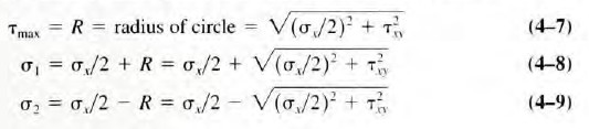
Pure Uniaxial Compression
Figure 4-30 shows pure uniaxial compression as it would be produced by a standard compression test. Mohr's circle shows that σ1 = 0; σ2 = σx (a negative value); and the magnitude of the maximum shear stress is τmax = σx/2.
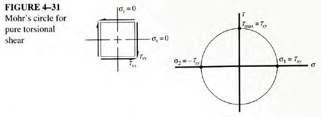
Pure Torsion
Figure 4-31 shows that the Mohr's circle for this special case has its center at the origin of
the σ-τ axes and that the radius of the circle is equal to the value of the applied shear stress, τxy. Therefore, τmax = τxy; σ1 = τxy; and σ2 = -τxy.
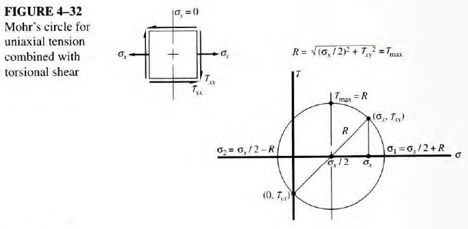
Uniaxial Tension Combined with Torsional Shear
This is an important special case because it describes the stress condition in a rotating shaft carrying bending loads while simultaneously transmitting torque. This is the type of stress condition on which the procedure for designing shafts, presented in Chapter 12, is based. If the applied stresses are called σx and τxy, the Mohr's circle in Figure 4-32 shows that
A convenient and useful concept called equivalent torque can be developed from Equation (4-7) for the special case of a body subjected to only bending and torsion.
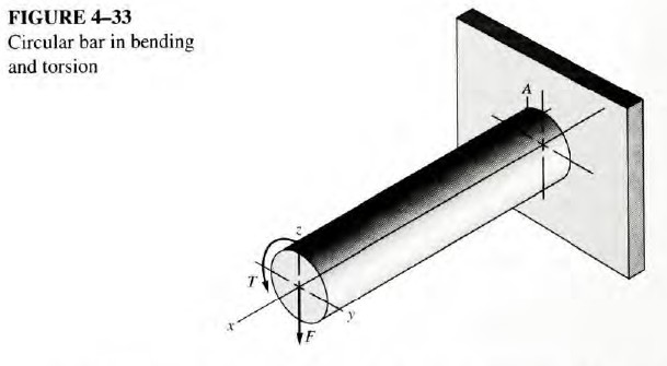
An example is shown in Figure 4-33, where a circular bar is loaded at one end by a downward force and a torsional moment. The force causes bending in the bar with the maximum moment at the point where the bar is attached to the support. The moment causes a tensile stress on
the top of the bar in the x-direction at the point called A, where the magnitude of the stress is
where S = section modulus of the round bar
Now the torsional moment causes torsional shear stress in the x-y plane at point A having a magnitude of
where Zp = polar section modulus of the bar
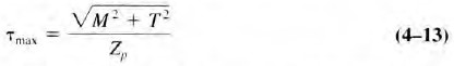
Point A then is subjected to a tensile stress combined with shear, the special case shown in the Mohr's circle of Figure 4-32. The maximum shear stress can be computed from Equation (4-7). If we substitute Equations (4-10) and (4-11) in Equation (4-7), we get
Note from Appendix 1 that Zp = 2S. Equation (4-12) can then be written as
It is convenient to define the quantity in the numerator of this equation to be the equivalent torque, Te. Then the equation becomes